Disabling the Local Control on a SR227 X-10 SuperSocket
Posted: 2019-December-29 Filed under: Electrical Leave a comment »X-10 is a system for controlling various modules (such as dimmer-controllable lamp modules and on/off only appliance modules) using signaling sent through the electrical system of a house. According to the Wikipedia article on the standard, the standard was created in 1975 and works on various international household voltages and frequencies. I have a system in my house which uses a Tandy Model 102 computer running my own BASIC program to provide home automation, interfaced to the X-10 system using a Marrick MA-RS232L LynX PLC Interface.
Most appliance and lamp modules had a feature called "local control" which worked by switching the appliance or lamp's switch off-on-off somewhat quickly to make the module switch on. I've generally disliked this feature as it fails in a couple ways. If if a device cycles on-and-off periodically itself (like a space heater), it will often trigger the local control and turn on unexpectedly. Second is if a device has "futuristic circuitry" (e.g. made after 1975) like switching power supplies or LED lamps it tends to trip up the local control circuitry and turn on automatically. Fortunately, it seems the designers realized some people would dislike the feature, so they often included a jumper wire right on the circuit board inside the module which could be cut to disable it.
I searched for an article specifically addressing the SR227 X-10 SuperSocket for the North American market (120VAC, 60Hz) but didn't find anything. This article on X10Community.com1Internet Archive link outlines the basics, including a circuit diagram for the appliance module, and is the basis for my own tests on the SR227. I took it apart and found it used the same 78570 chip as the appliance module in the aforementioned article.
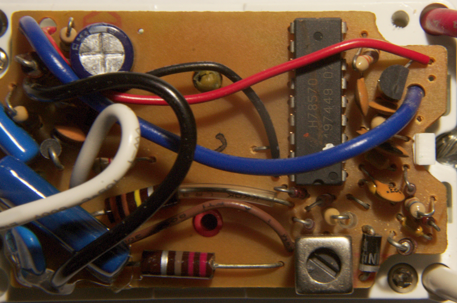
SR227 Circuit board top.
As it turned out, there was indeed a jumper tied to pin #7 that could be cut.
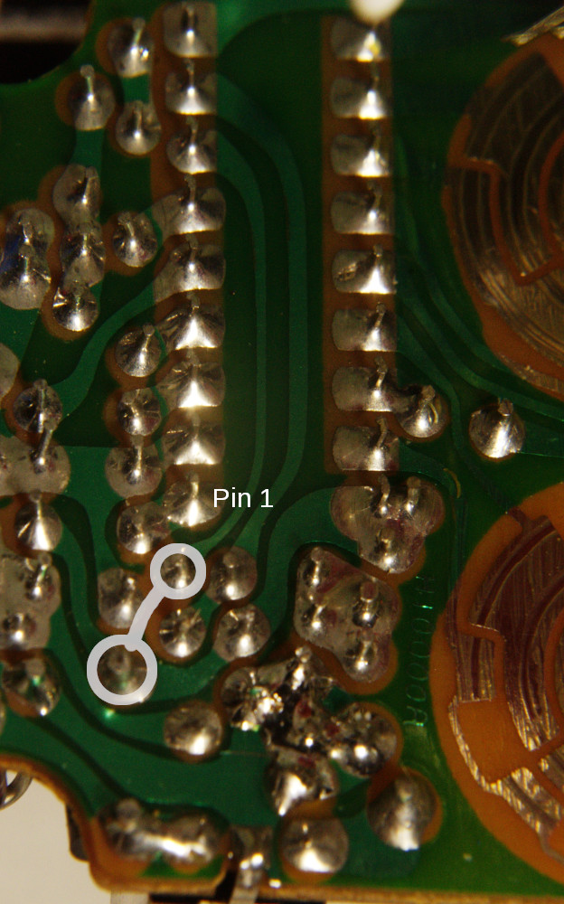
SR227 Circuit board bottom.
It is located near pin 1 of the 78750 chip next to the diode. There is a second jumper near pin 16 but it is part of the circuitry to select the module and house number.
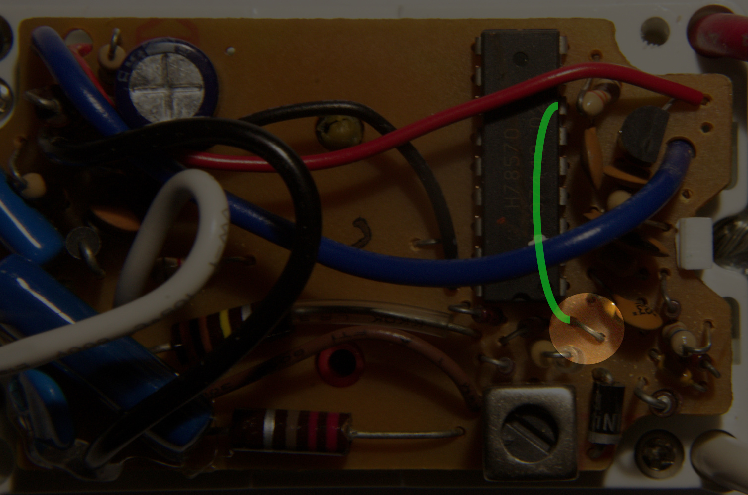
SR227 Circuit board top with jumper and trace highlighted.
You might have noticed that my module has a red wire that comes through the electrical wiring hole near the upper right corner of the circuit board. I soldered this to the relay output so the inside of the electrical box could have access to the controlled circuit. In fact, that's specifically why I wanted to use this module: simply to have a switch for a circuit inside an electrical box. If you have enough experience with electronics, it is obvious where and how to solder on such a wire. (Not to be too snide, but if it's not obvious, please refrain from attempting it.)
Recent Comments