SIP 7-Segment LED Display Adapter
Introduction
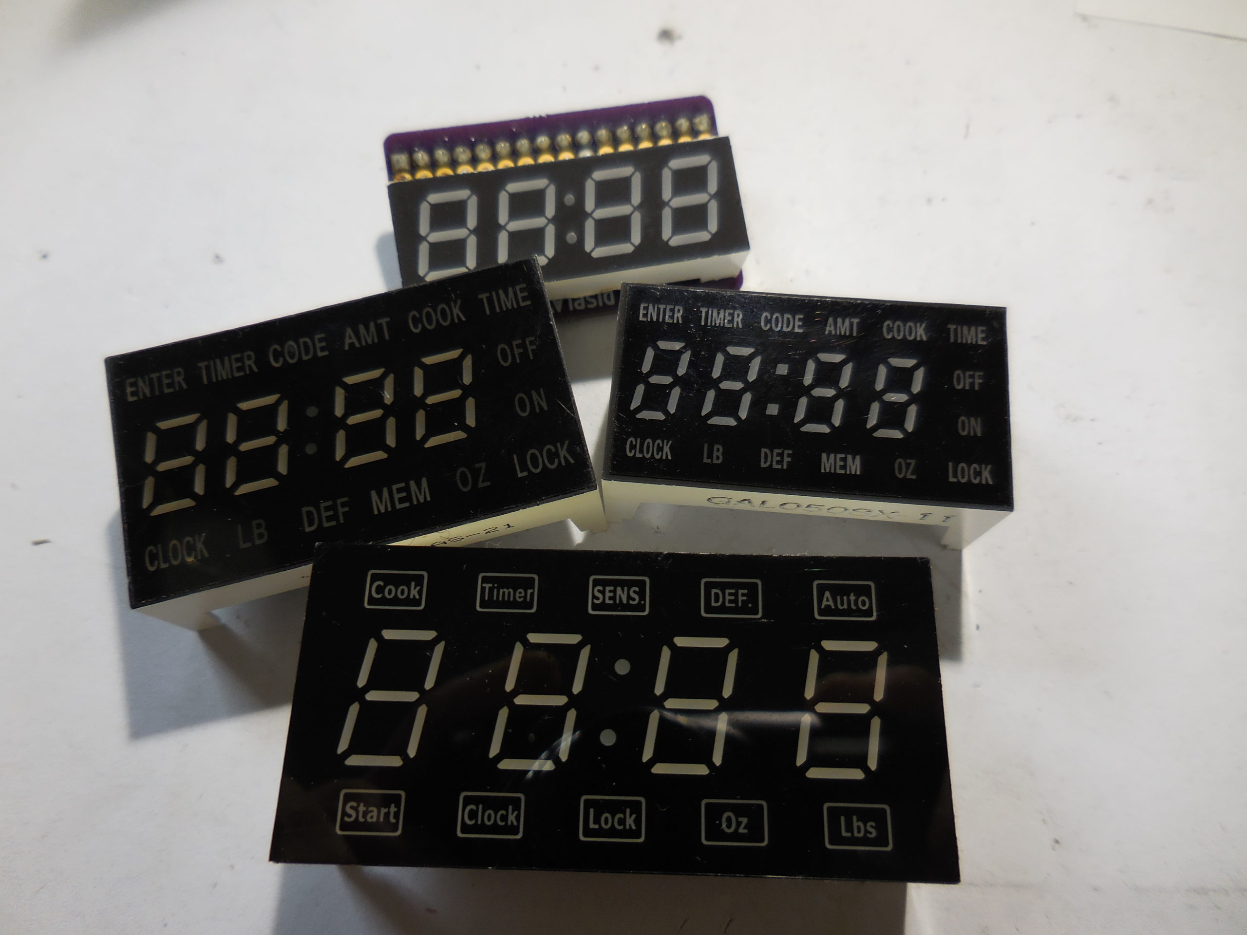
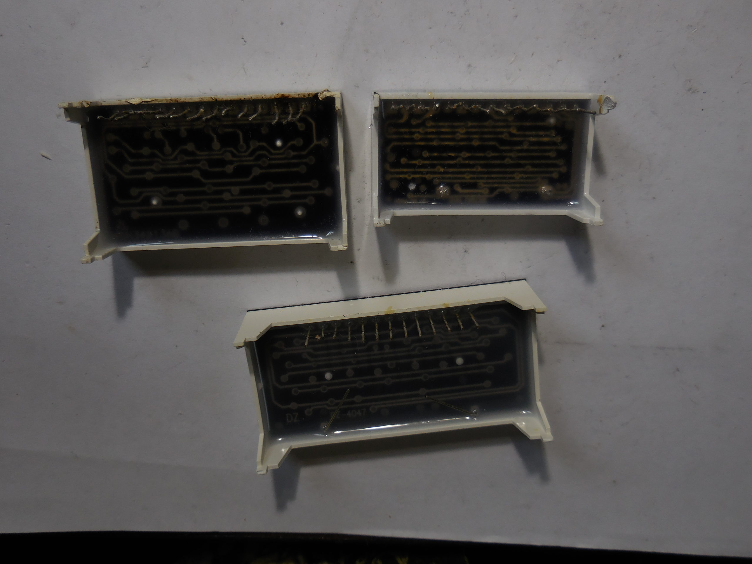
I'll often scavenge parts from various products and electronic waste around where I live. A common item is microwave ovens which have a lot of neat things inside. Very often, they include a LED 7-segment display which is connected to the circuit board as a single-inline package (SIP). Each display seems to be pretty similar but none of them have the same pinout. The basic layout is that there is a common pin for each digit's LEDs, connecting either all the cathodes or anodes. The like segments of each digit are then also tied together to separate pins. That way, to make a single segment light, one would run current through the digit-select pin and the segment-select pin to identify a single LED.
What I would like to be able to do is to connect these displays to a microcontroller. My go-to is Microchip PICs (never got into Arduino), and the I/O pins can drive an LED directly since they are current-limited to 20mA. However, the digit select pins would need 7 × 20mA = 140mA to display an 8 (all 7 segments on) which isn't available.
History
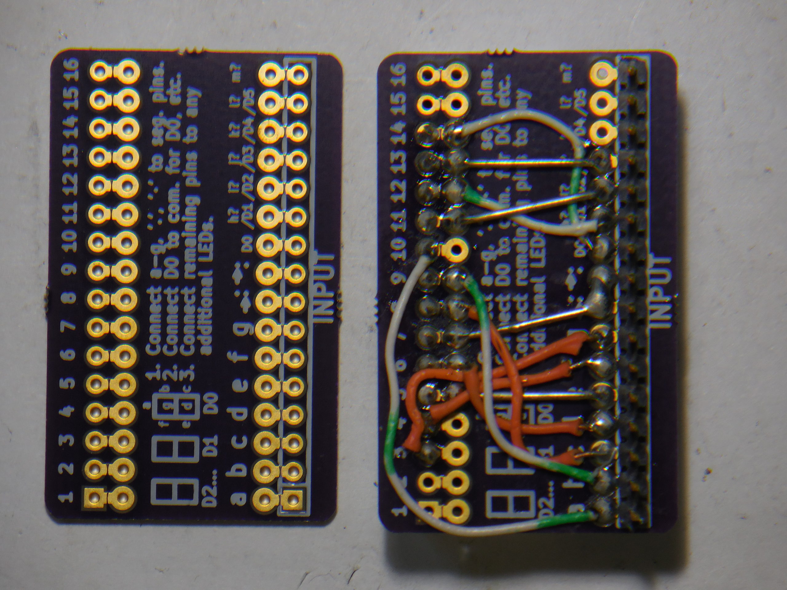
At first I was trying to get all the pins rerouted to some "standard". As such I made a board that just let you run jumper wires. It's the way the top clock display is connected in the picture. The trouble was it was a mess to wire. I did get all the outputs organized, but it had no driver capabilities built in. It wasn't terrible but clumsy and messy to wire up. I also realized that a SIP connection alone is not very structural so the board would flop around a little, potentially breaking the pins (that's why the pulled displays have plastic legs for physical support.) In general it's a no-no to have solder connections be both for structural connection and for electrical connection at the same time.
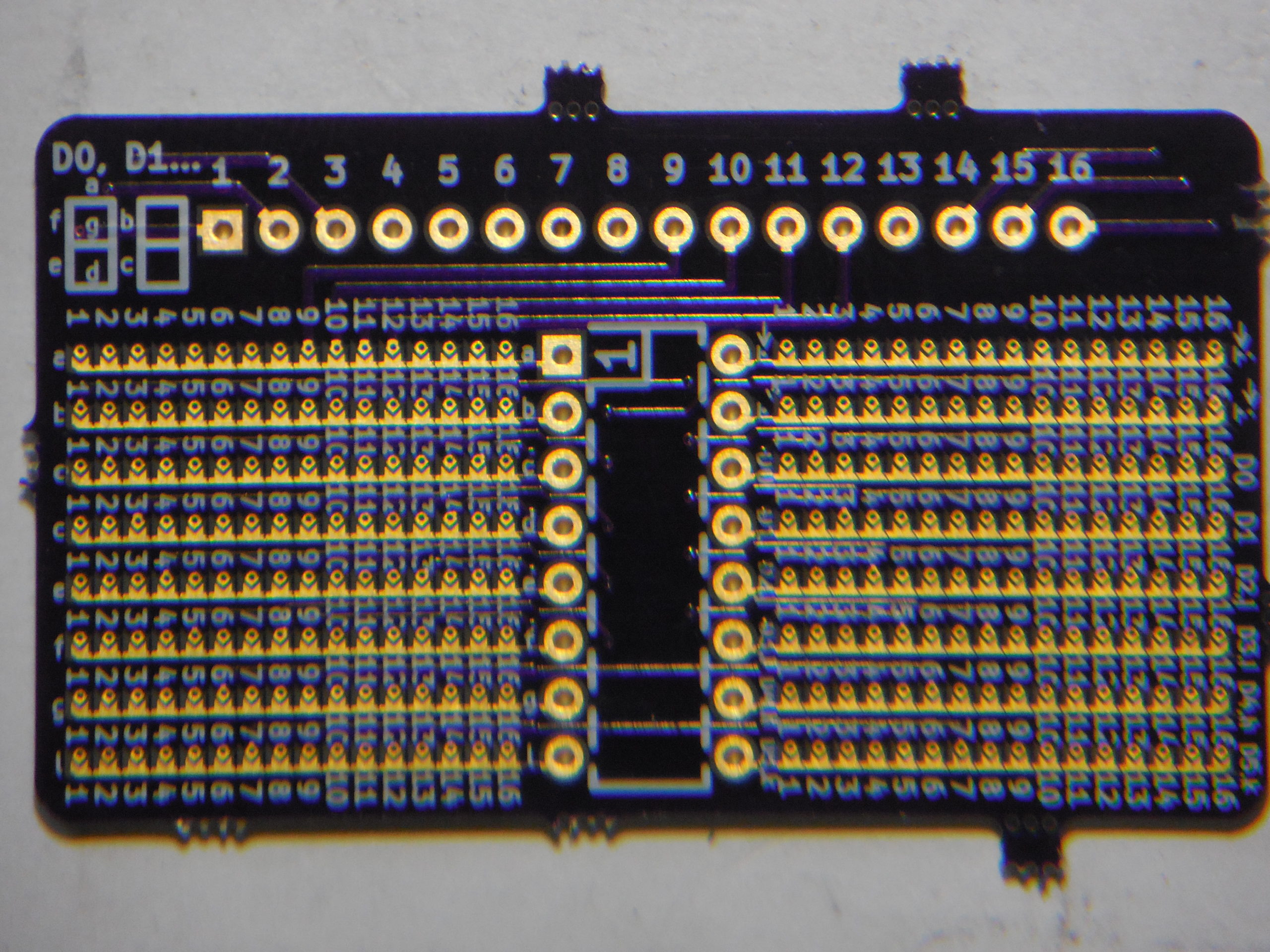
So then I thought I'd make a board with solder jumpers to make it all tidy. I spent a fair amount of time making a tiny solder pad with a via built in so I could couple one column to one row. I also switched to a DIP layout to make a more stable base. The only trouble was it was really really dense and quite difficult to hit the right connection. I think it's kind of a neat idea, but I never even connected a display to try it. It sure looks pretty cool, if I say so myself.
I put the project aside for a few years and got back to it in 2020 since I wanted to use these displays. I realized that the microcontroller software was pretty easy to modify, so routing the pins to some perfect standard with digits and segments split out was not all that useful. What was an issue was what I mentioned earlier: driving the common pins.
Operation
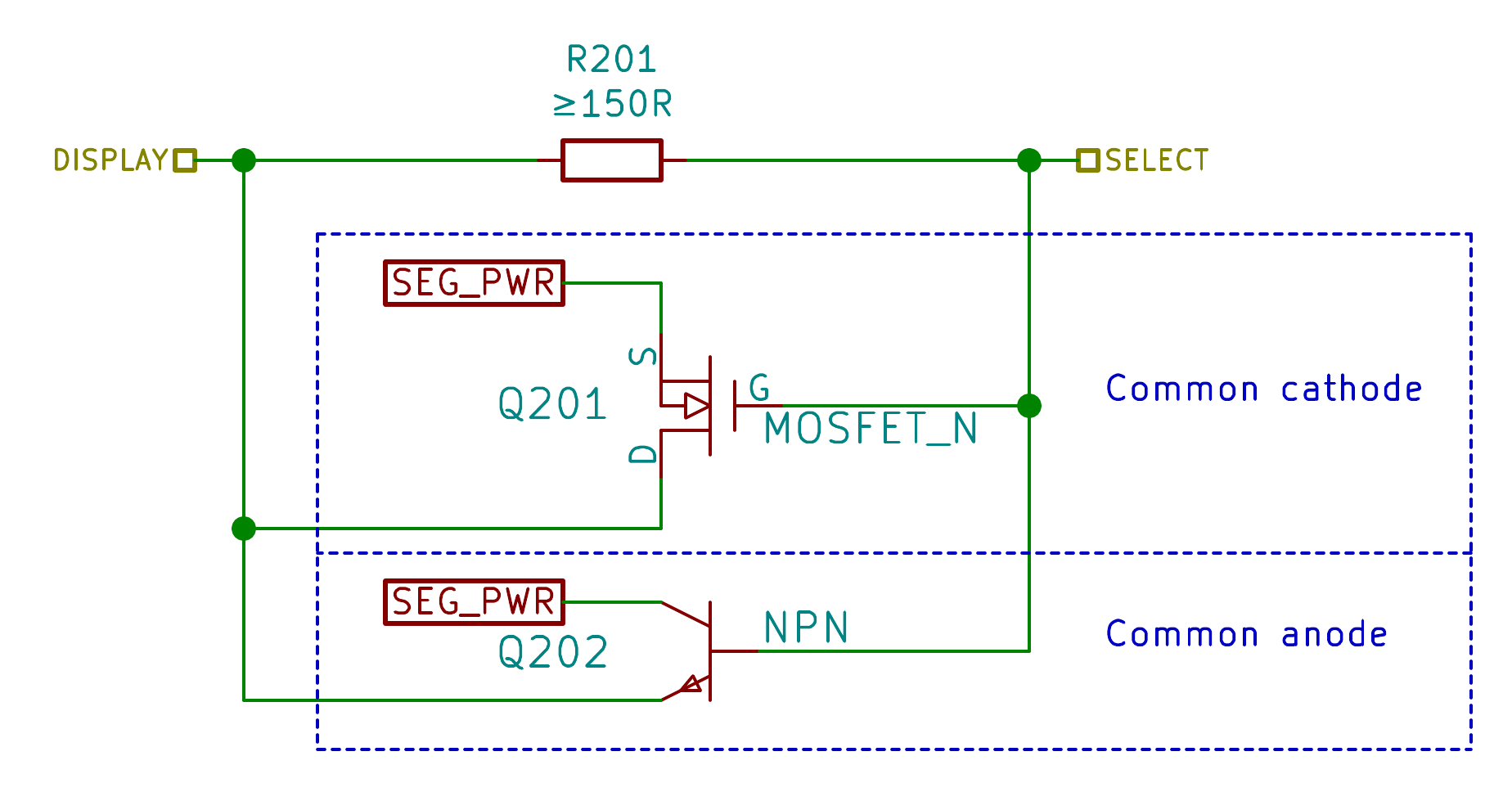
My latest design is to use a partial-population technique to select the function of each pin on the SIP display and route it to a pin on a DIP-style package. There are three options: a current-limiting resistor (or simply a solder bridge if you don't need current limiting), an NPN transistor to drive the pin to +5V, or an N-channel FET to pull the pin to 0V. In the key part of the schematic shown, the SEG_PWR is a global connection which has a solder jumper to either pin 18 (ground) or pin 17 (+5V).
Since this is for hobbyist use—and customized for each display—I'm assuming hand-soldering so the resistors and transistors are mounted on both sides: top for even and bottom for odd just for space. Also, the transistor package outlines overlap since only one will be installed. For space considerations, I decided on surface-mount transistors with a SOT-3 package along with 0603 resistors.
You may have noticed that all this time I've been supporting up to 16 pins on the SIP which I think is overkill since I've only ever seen 13 pins used. Nonetheless, if you use two 8-bit shift registers to drive the displays, that nets you 16 pins to work with. The new design, however, adds a +5V and 0V pin, so the DIP got bumped to 18 pins which is a little odd and potentially annoying if you have a lot of 16-pin sockets you'd like to use.
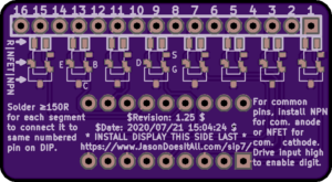
Starting at the back of the board, it's not overly interesting. You can see that below the SIP there are pads for resistors, then the overlapping outlines for the NFET and NPN. The pins of each are called out below pin 9 and pin 13 of the display for reference. The display will eventually be mounted on this side, but the components and DIP need to be installed first since the display will cover this side of the board. I added the CVS revision information, URL, and some instructions for assembly on this side.
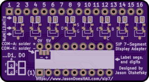
The front side will, I guess, end up being the bottom of the display and ultimately mounted to a circuit board so hidden. Nonetheless, it's way prettier and dynamic. The even pins get the resistor/transistors treatment like above, and the transistor call-outs are on pins 8 and 12 this time. As noted before, pin 17 is specified as +5V and pin 18 as ground. There is a solder jumper below that to select either voltage as the common—0V if the display has common cathodes, or 5V if the display has common anodes. (Do not connect both or you'll short out the power rails.) There's a big white silk screen where you can attempt to write in the function of each pin. There's a diagram of the 7-segment display with the industry-standard lettering of each segment for reference, so you can label the top middle segment "a" on the DIP, etc. I recommend "D0" for the least-significant digit of the display then increment to D1 for the 10s place and so on, but that's just my preference. Any additional functions like the ":" or decimal points can be called out as well.
The holes should be just big enough to let you use square SIP pins in each row of the DIP. Or you can use cut-off leads from through-hole components (you save those, don't you? :) ) which will work better to fit into a DIP socket.
Once it's all wired up and installed, the microcontroller should be programmed to address the digits as they appear in your circuit. The nice part now is that to select a digit, you just need to drive the display pin with +5V: if an NPN transistor is installed, it acts as a buffering current-amplifier of the voltage on its base, and if an N-channel FET is installed, it acts as a switch to ground when its gate is pulled high. The microcontroller will need to know the polarity of the display since the segment pins need to be pulled low for a common-anode display or high for a common-cathode display.
Availability
As of 2020-Jul-21, I ordered some sample boards to start with but I haven't had a chance to test them. Nonetheless, here's the pertinent links:
- Order boards from OSHPark.
- 20200721 SIP LED 7-Segment Display Adapter v1.25 Gerbers.zip to be used with pretty much any circuit board manufacturer.
- 20200721 SIP LED 7-Segment Display Adapter v1.25 KiCAD source.pdf made with KiCAD v5.0.2.
- 20200721 SIP LED 7-Segment Display Adapter v1.25 Schematic.pdf (which includes 16 copies of the same selection circuit but with different part numbers.)
- 20200721 SIP LED 7-Segment Display Adapter v1.25 Layout.pdf with all the board layers on a separate page.
Recent Comments