Try to write cool software; settle for functionality
Posted: 2005-August-19 Filed under: Computer, Projects, The Bike With 2 Brains Leave a comment »Friday morning I started working on the bit modulation. I needed to have some kind of indirect addressing to access the three colors on each of the 22 LED's and convert each one to bit patterns to output. I looked through the documentation for the processor and they had functions for accessing tables, but after looking closer, I found that it was designed to access the flash memory and I don't really want to wreck the flash memory reading-and-writing it over and over again.
I looked into the macro features of the assembler but the only flow control is "while" and "if/else" statements. I hacked together some stuff to access arrays in macros, but it's crap, gobbling up both program space and CPU time
I finally found information on the "FSR" ("file select register") that does exactly what I want: you load one of the three FSR's with a RAM ("file") address and then use INDFx as an operand (in place of, say, an absolute register address) and it'll use the FSRx pointer.
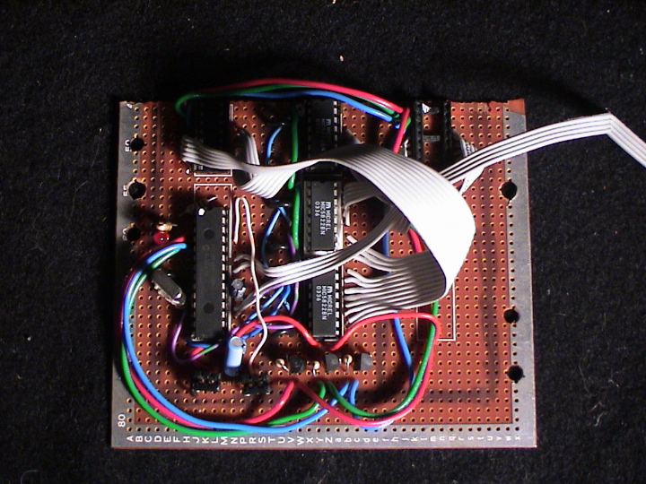
I got the confidence to plug in one of the shift registers. I had to fix the code so it'd load the shift register properly and to latch the output, and also to turn on the output for a color LED. That was awesome: apparently my hardware was wired correctly and worked on the first try. I added in the other two shift registers and it all worked great.
On Saturday I got up around 4 a.m. and got going. I cranked out code to convert 8-bit color values into bit-modulated registers ready for shifting-out to the hardware. I got the whole bit modulation system partially working. I ran through the code several times and picked out and fixed a bunch of little bugs. I was worried that I was getting some kind of race condition that was causing things to flicker randomly instead of actually work, but timing adjustments had no effect at all. I finally found a huge logic error with the way the bit modulation was loaded. I rewrote it much better but it still didn't work.
I stripped things down a bit to do some tests. I tried to use the code I had to output to the shift chips by making a simple alternating-light blink pattern. It worked fine, and even changing colors in software worked. I tried the same thing only using the "fast" clock rate and also switching colors from red to blue and that worked fine too.
Sunday I got up around 4 a.m. again. I wrote the code to control the MP3 player real quick and got it working in no time. I added code to check light levels and got that working: the circuit is just a 100K resistor from +5V to a CdS cell to ground. When it's light, the CdS cell's resistance is much lower than 10K so the voltage present is a logic "0" at 0.5 volts; when it's dark, the CdS cell's resistance is higher than 1M, so the voltage present is a logic "1" at 4.5 volts.
I went through the rest of the code looking for misspelled op-codes (that is, MOVFW and MOVWF do very different things) but no luck. I changed the code at the beginning to initialize things better and set up the test case to be very simple: 2 LED's on, red #10 at 100% and blue #11 at 25%. I got two greens on: #7 and #10.
I'm not sure what the deal is there … it doesn't seem like there's a good explanation why it isn't going to the right place. I checked the wiring and found that the latches are wired so the first LED is output #8 on the MIC5822, so I reversed the rotation order in the bit shifting algorithm.
Ok, I finally gave up and went with a simple pulse-width modulated output. The idea is to slowly cycle through the spectrum from red-to-green, green-to-blue, and blue-to-red. I set up the code to modulate between "color 1" and "color 2" slowly shifting the duty cycle from 0% to 100% on "color 1" and from 100% to 0% on "color 2" along with an off-cycle to make it dimmer and use less power.
I got it all done and running on the battery pack — the whole thing, lights and audio included, runs at about 2 watts.
![]()


Recent Comments