Generators #6: Now With Stronger Magnets
Posted: 2005-May-15 Filed under: Power Source, Projects, The Bike With 2 Brains Leave a comment »I drilled shallow holes and glued the rare earth magnets to a wood dowel to try them out as a generator rotor. They really are strong and tended to pop out of the glue to stick together. I managed to get it built with two poles but it didn't make an appreciable difference in the performance of the generator.
![]()
Generators #5: The Permanent Magnet Rotor
Posted: 2005-April-24 Filed under: Power Source, Projects, The Bike With 2 Brains Leave a comment »I glued a couple magnets onto a wooden dowel with a screw through it to make a permanent magnet rotor. The magnets aren't particularly strong, and my first attempt had the poles opposite one another: that is, the north on one magnet mated with the south on the other, so the field was even weaker. (This all fit into the field coil from the Dirt Devil motor.) At 3,100 rpm, I could output 53 Hz AC at 2.7 volts open, 2.1 volts into 51 ohms (0.086 watts) and 0.7 volts into 3 ohms (0.16 watts).
While this isn't particularly promising, I purchased a pack of 50 0.25" diameter neodymium rare-earth magnets from K&J Magnetics. They're supposedly rated at N45 which I guess is almost as strong as you can get.
![]()
Generators #4: A New Hope — AC generators
Posted: 2005-April-2 Filed under: Power Source, Projects, The Bike With 2 Brains Leave a comment »I figure I can easily convert a DC motor to an AC motor by tying one side of the rotor windings to both sides of the brush assembly rotor thing, and the other side to the shaft. That way I can step up the output voltage to a useable level.
I went to the basement and grabbed all the motors. I decided to try converting the drill motor since it generated the highest current (next to the original) and it's the largest. I decided against the air pump motor because, although it can source a lot of current, the output voltage is so low it's almost not worth it … then again, that's based on running it up to 3,100 RPM on the drill press, not the huge speeds from spinning on the rubber wheel.
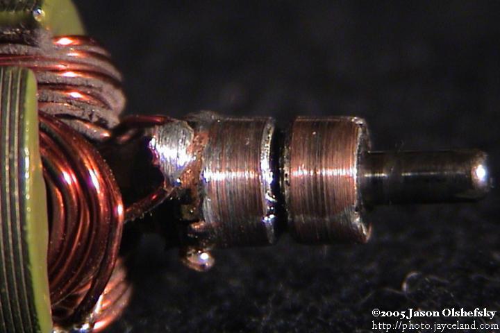
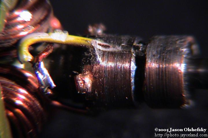
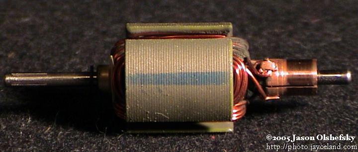
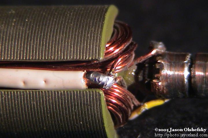
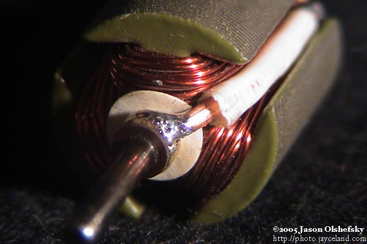
Anyway, I took apart the gold-colored motor and rewired it. I started by cutting a groove around the commutator and soldering the original poles together so I ended up with a 2-pole slip-ring instead of a 3-pole commutator. I ground down the brushes so each would contact one pole of the slip-ring. I disconnected the three poles, undid the connection that tied the windings in a loop and connected each end to the slip-ring contacts.
When I reassembled it and tested it, I roughly zero volts out. I had successfully demonstrated that the motor was wired efficiently and Kirchoff's laws still apply: of course there was no current flowing at that point — otherwise, when run as a motor, it would short-out. Dummy.
I took it apart again and wired it for 3-phase. Two phases were wired to the brush output, and the third was soldered to the shaft bushing so I could use the case as the third phase. It sort-of worked, but then the wire I was using to tie the third leg to the shaft came loose and wedged between the rotor and the magnets.
I reassembled the motor with a stiffer wire. I found that the brushes would bounce on the imperfect rings I had so they wouldn't transfer the power. I could get up to about 1 amp of output on any one coil and up to 1.5 volts or so. I cleaned up the rings and such but couldn't get them round enough with the tools I had so I gave up on it.
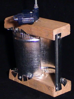
However, I also had an AC brush motor from a Dirt Devil hand-held vacuum and figured I could make a rotor with permanent magnets to induce current in the outer coil. Finally a break in all this: the rotor shaft was 5/8" which is the same size (well, 8mm) as the the bearings I bought for the Savonius rotor. Even better, the magnets in the gold-colored permanent magnet motor are very close to the right size.
![]()
Generators #3: Experimentation
Posted: 2005-April-1 Filed under: Power Source, Projects, The Bike With 2 Brains Leave a comment »I tested some of the motors at high-speed to see how much they'd generate and to see if any would be suitable. Note that the motor speed was dictated by the shaft diameter; the drill motor, 6V motor, and original motor had larger shafts and ran slower.
Motor
open
voltage
voltage
@ 3 ohms
power
@ 3 ohms
drill
> 4.7
4.6
7.0 watts
gold
> 4.5
4.6
7.0 watts
silver
> 3.0
3.7
4.6 watts
6V motor
> 6.5
4.6
7.0 watts
original
> 14.0
7.5
18.8 watts
For the stepper motor, at 1,100 rpm, using both phases through a bridge rectifier, it would source 0.63V into 3 ohms or 0.13 watts. One phase through a 5:1 step-up transformer frustratingly yielded the same results: 0.6V. Both phases in series yielded 0.67 volts, and at 1,720 RPM, 0.8 volts. The open voltage on the transformer secondary was 11.75 volts.
I also took apart one of the pumps that I used to use for the air horns in the car and got its motor separated. It could source 3 volts into 3 ohms and had a short-circuit current of 5 amps at 3,100 RPM.
![]()
Generators #2: Stepper motors suck as generators
Posted: 2005-March-31 Filed under: Power Source, Projects, The Bike With 2 Brains Leave a comment »I decided to go buy a motor so I went to Glenwood Sales (549 Hague St.) and browsed for a while before eventually settled on a 30 V stepper motor with a 48 ohm coil. It apparently has 4 phases, and each phase would ordinarily consume 0.625 A or 18.75 watts.
The stepper motor could generate as much as 50 volts open-circuit (it's wired with two coils center-tapped.) Through a 51-ohm load I found it could get as high as 5 volts, and through a 280-ohm load, 20 volts. The good news is it's pretty linear from about 1,000 RPM through 3,000. The bad news is those two ratings yield only 0.5 watts and 1.4 watts respectively.
Using a full-wave bridge on each side and tying the outputs together and running at 3,100 RPM, I could get 9 volts into 51 ohms and 34 volts into 280 ohms: 1.6 watts and 4.1 watts respectively. Open, it would generate 90 volts. Indeed, none of the motors would source more than a half a volt at 3,100 RPM; one that I hadn't tested would generate 0.5 V and 1.5 amps, so at least that's promising.
![]()
Method of mounting the rotor bearings; Generators #1: These generators suck
Posted: 2005-March-28 Filed under: Power Source, Projects, The Bike With 2 Brains Leave a comment »I found that I have some 1" thin-walled tubing from an exercise machine that has a nearly 22mm diameter — the outside diameter of the bearings I bought. I figure I can weld a piece of tubing to the ends of the windmill frame then cut a slot and use a seat-post clamp to grip the bearing.
I also tested the motors I had selected as candidates for a 10-watt generator. None of them performed better than the motor I had originally selected.
Based on my former calculations, the rotors would only run at 300 RPM in a 10 MPH wind, so a 7x gear-up would only yield 2,100 RPM which wasn't enough to generate any appreciable power. To get any power out, I had to run the baby carriage wheel in the drill press at 620 RPM with a 0.33" gear, so the ratio to the 7 3/4" wheel (23.5x) means I ran the motor at 14,500 RPM. If this were 20 mile-per-hour wind, then a 70 mile-per-hour wind would overcrank the motor to over 50,000 RPM and probably blow it up. I'll have to see how slow I can get the motor to run and still get decent power. Well, I know that 3,100 RPM is not enough: the motor, when hitched directly to the drill press, would only generate about 3.4 volts open and 1.9 volts into 3 ohms (only about 1 watt.)
Ok, so let's say I limit the motor to 15,000 RPM at maximum wind speed of 70 MPH, or 2,100 RPM. The ratio, therefore, is 7:1 … bummer. I think I'm going to need to get a different motor. If I use 21,000 RPM as the cap, I can get to a ratio of 10:1, so in a 10 MPH wind, the rotors would only run at 300 RPM driving the motor at 3,000 RPM which isn't enough.
![]()
Buy ball bearings
Posted: 2005-March-3 Filed under: Power Source, Projects, The Bike With 2 Brains Leave a comment »I hunted around on the Internet for ball bearings to fit a 5/16" shaft but wasn't having any luck. When I switched to metric — realizing that 5/16" is just 0.8% shy of 8mm — I discovered that I should be looking into inline skate bearings. I bought a pack from Pleasure Tools.
![]()
Survival calculations
Posted: 2005-February-28 Filed under: Power Source, Projects, The Bike With 2 Brains Leave a comment »I wondered what kind of forces the windmill will need to reckon with in strong winds. I found a g-force calculator on the Internet and determine that a 9.2-inch rotor (4.6-inch radius) running at 2,100 RPM (the speed I calculated for a 70 mph wind) will exert 578 g. Therefore, if there's one ounce of material at that radius — ergo an imbalance of one ounce — it will exert 36 pounds of force. Although I think 5/16" rod will easily handle 36 pounds of force, it's the 30 cycle-per-second vibration that might kill something.
I guess I have to be careful about balancing it.
![]()
Savonius rotor test
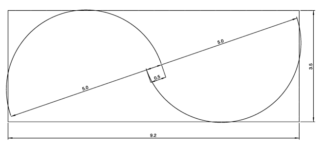
Posted: 2005-February-18 Filed under: Power Source, Projects, The Bike With 2 Brains Leave a comment »I thought I bought 6" round duct pipe, but apparently it's actually 5" in diameter. Anyway, I played with it a bit and figured I could make a neat rotor using a 2×4. I put it in the CAD software to get the dimensions (note also that I'm using a 10% gap between blades at the axis which is recommended by most people.
The idea was to notch the ends of the pipe halves and bend them into tabs to screw onto 2×4's. I wanted to ensure that one tab extended to screw into the end of the 2×4 and that the arc of the pipe fell tangent to the edge of the 2×4 so I could put another screw in the side through a tab. What I found was to cut the 2×4 to 9.2 inches long.
I learned that it was important to ensure the bent tabs form parallel planes. My first rotor came out crooked … not by too much, but enough that it would vibrate like mad in even modest wind. (By the way, that's the axle from a baby stroller wheel that I used as a pivot point to test it.) That, and I should alternate my cut tabs inward and outward so they don't overlap on the inside of the curve. Oh, and that you can only screw into tabs that are on the outside of curve — I guess unless you've got a short screwdriver or make the pipe segments longer than I did.
The best part, though, is that the rotor is very rigid. I'll be more diligent about the next design, and I sure hope it will survive strong winds.
![]()
Computer hard drive windmill
Posted: 2005-February-2 Filed under: Power Source, Projects, The Bike With 2 Brains Leave a comment »I started with the spindle motor from an old hard drive. I figured it was a pretty nifty use: the permanent magnet 3-phase motor should make a cool generator, plus it will supply 3-phase power. Unfortunately, my hopes of hitting 20 watts with it are pretty much dashed.
I cut out a Compuserv CD into fan blades, heated it to bend them, and mounted it to the motor. With the air hose, I managed to get to 600 RPM (a far cry from the rated 5400 RPM) and dumped 30 volts into 1000 ohms for a power output of 0.9 watts. Indeed, the power rating on the drive indicated it was only supposed to draw about 6 watts total, so my chances of getting past 5 watts or so is not too likely. However, even 5 watts over 20 hours would provide me with enough power to run 10 watts of lighting and other stuff for 10 hours or so. At least the 100 watt-hours generated each day is far more than the 50 watt-hour capacity of the batteries I'm looking at. Oh, then I broke the blade.
![]()

Recent Comments